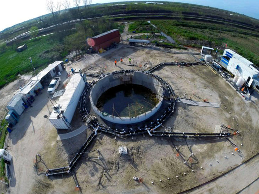
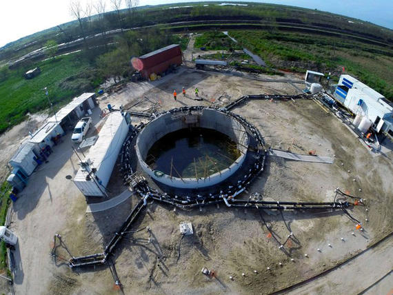
When Access Shaft #3 experienced persistent soil and groundwater ingress during excavation, Keller was contracted to design, furnish and oversee the installation of a ground freezing system to provide a watertight barrier that would allow the general contractor to install the final concrete liner.

The project
The Sistema de Potabilización Area Norte project will transport and treat raw water from the Paraná River, providing potable water for 2.5 million residents in Northern Buenos Aires province. The overall project includes a 9.3-mile long, 11.8-foot diameter bored tunnel, five access shafts, and eight ventilation shafts.
The challenge
The tunnel was bored by two TBMs at 59 to 72 feet below ground level. At the location of the 35.4-ft diameter Access Shaft No. 3, subsurface conditions consisted of approximately 26 ft of soft sandy silt overlaying strata of soft clay, firm sandy silt, and very dense sand. Hard clay was encountered at a depth of approximately 160 feet. Groundwater was located within five feet of the ground surface. Given this profile, Shaft No. 3 was designed to be excavated within a “bathtub” consisting of a 98-foot deep structural slurry wall with a jet grout bottom seal. During initial excavation, however, leakage between the wall panels led to inflows of water and soil. The joint venture prime contractor, Aguas del Paraná UTE (ADP), flooded the shaft and initiated a program of tremie grouting to seal the leaks, but further leaks were encountered during shaft cleanout. Over the next 14 months, as further leaks continued to be encountered, ADP employed various remedial efforts including tube à manchette grouting, jet grouting, and dewatering, all without success. The shaft was eventually filled with lean concrete above the tunnel crown to allow passage of the tunnel boring machine while the shaft remained flooded above.
The solution
ADP subsequently contracted Keller to bring its significant ground freezing experience to the resolution of the issues by designing and furnishing a ground freezing system to control the leakage and provide field engineering and on-site supervision during freeze pipe installation by ADP’s drilling subcontractor. Keller also monitored ground freezing operations through final liner installation.
Keller conducted finite element thermal analyses, using TEMP/W software, to estimate the total heat load and the time required for closure. Structural analyses, conducted with Plaxis 2D and Plaxis 3D, were used to estimate the force of frozen soil against the existing concrete shaft and tunnel. The structural model was refined with input from ADP’s structural consultants, who designed a bracing system to be installed inside the tunnel to withstand the forces generated by soil expansion during the freezing process. Keller also designed a system of contact cooling rings to be installed in the existing tunnel to maintain low temperatures in the concrete liner, thus ensuring a continuous bond with the frozen soil outside the liner segments.
All ground freezing equipment, including pipes, fittings, tanks, instrumentation and data acquisition system, and two mobile freeze plants with a combined refrigeration capacity of 281 tons, was shipped from Keller’s New Jersey office. The installed system consisted of 48 vertical freeze pipes around the shaft perimeter, 25 angled freeze pipes installed around and beneath the tunnel, and seven temperature monitoring pipes. Freeze pipes consisted of 4.5in. OD steel pipe terminating in the hard clay layer.
Calcium chloride brine chilled to -27°C was circulated through the pipes during system operation. After nine weeks of freezing, closure was verified by temperature and piezometer data, allowing ADP to pump down the shaft, install the base slab reinforcement, and install the final concrete liner. The shaft remained dry and stable throughout.
