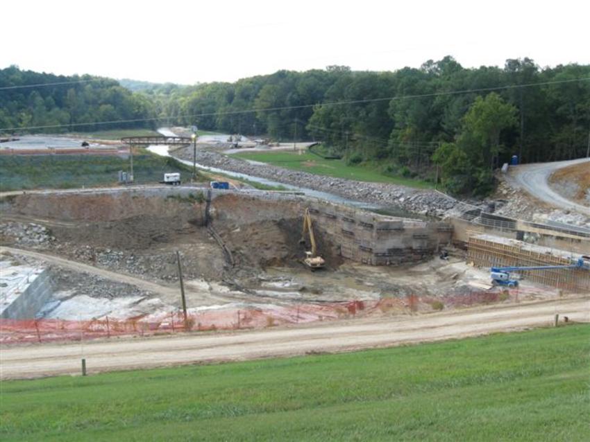
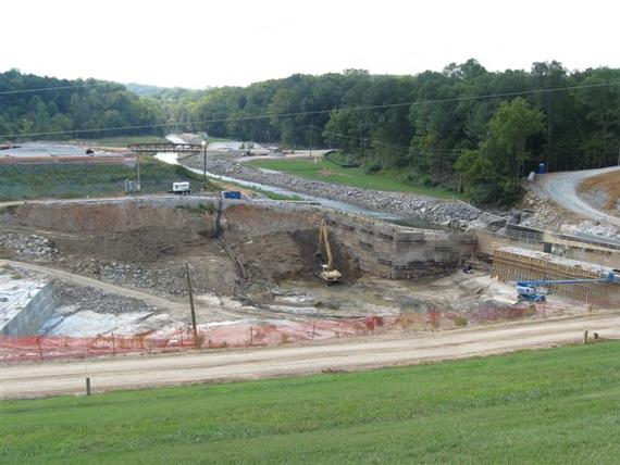
Keller performed construction dewatering and excavation support during the Bear Creek Dam remediation program.

The project
Bear Creek Dam, a 68-foot-high earthen structure with a crest length of 1385 feet, retains a 12-mile-long reservoir. The dam is founded on fractured karstic limestone, consisting of Upper and Lower Bangor Limestone separated by a stratum of Pennington Shale.
The challenge
From its construction in 1969, the dam had experienced excessive foundation seepage, compromising its structural integrity. Efforts to control the leaks had proved to be effective only in the short term. Following an in-depth evaluation of viable long-term solutions, the Tennessee Valley Authority (TVA) initiated a remediation program that included the installation of a grout curtain groundwater cut-off beneath the existing dam and constructing a roller compacted concrete (RCC) buttress at its downstream toe.
The solution
To facilitate construction of the RCC structure, Keller was contracted to install the following:
- a deep well system to intercept groundwater in the fractured karst formation
- an eductor system to dewater the overburden and overburden/rock interface
- a soldier pile and lagging support systems with tiebacks for excavation to subgrade at the existing spillway and the in-service sluiceway.
Dewatering was performed on the upstream and downstream sides of the excavation for the RCC dam. The dewatering system's intent was to lower the groundwater table below the excavation subgrade for foundation construction. The prevailing subsurface conditions and anticipated flow rates determined the type of dewatering system, method, and well components.
In addition to the wells, Keller also installed multiple sumps on the upstream slope just above the excavation in the event of seepage through the existing embankment during high reservoir levels from flood events. These conditions were not expected but needed to be anticipated.
Thirty-three deep wells were installed for dewatering of the rock. At each location, air rotary drilling techniques were used to advance a 10-inch diameter borehole, cased through the overburden, into the rock. The extent of rock drilling varied from as little as 8.5 ft to 101 ft, with 20 to 45 ft being the average. Elements of well construction included the installation of PVC high-flow wellscreen installed from top of rock. A pump test was performed on each well to determine its anticipated flow rate. Pump/motors ranged from 5 to 30 HP in the wells.
Near the existing sluiceway, a permeable layer of overburden existed that needed to be addressed with a closely spaced dewatering system. However, a sand and gravel layer in thickness from inches to up to nine feet, was present at the overburden/rock interface at a depth from working grade that precluded single-stage wellpoint dewatering. A single-pipe eductor system was therefore specified.
A total of 85 ejectors were installed along benches upstream and downstream of the excavation. Sonic drilling methods were used to advance 6-inch boreholes at 5-foot spacing to top of rock. The wells consisted of a 3-inch diameter screen, ranging in length from 5-10 feet, and sand filter pack. Each ejector line was connected to a central surface pumping unit powered by commercial power with generator backup.
Dewatering operations continued for 16 months until the RCC structure's construction reached an elevation where it could be backfilled. The total system—deep wells, eductors, and sumps—handled flows in excess of 4,000 gpm at times. Pumped water was channeled to the existing sluice for discharge.
During dewatering operations, the on-site engineer retrieved data daily from an array of piezometers and inclinometers to verify system efficiency. The piezometers were used to verify groundwater conditions and the effectiveness of the dewatering systems. Inclinometers were monitored to check for ground movement on the existing dam embankment due to construction.
All wells were filled with cement grout and abandoned on-site upon completion of the project.
